A slip ring — also called a rotary electrical joint or collector ring — transfers electrical power and signals across a rotating interface without restricting rotation. In an ROV winch or cable reel system, the slip ring allows the drum to rotate freely while maintaining continuous electrical connection between the stationary vessel supply and the moving cable. Selecting an inappropriate slip ring is a common source of system downtime, signal degradation, and premature component failure. This guide provides the engineering framework for correct slip ring specification.
When an ROV is deployed, the umbilical cable is wound on a motorised drum. As the drum rotates, any electrical connection between the topside electronics rack and the cable must rotate with it. A fixed cable cannot rotate — doing so would twist and ultimately break the conductor. The slip ring solves this by providing a path of metal-to-metal (or fibre-to-fibre) contact that rotates continuously without tangling.
A typical ROV winch slip ring assembly must transfer:
Gold-to-gold or gold alloy contacts are the standard for signal and low-current circuits. Gold does not oxidise, so contact resistance remains stable over millions of rotations. Contact force is low (typically 0.05–0.2 N), which minimises wear. Gold contacts are suitable for circuits up to approximately 5 A; above this threshold, resistance heating becomes problematic.
Silver graphite brushes are used for high-current power circuits. The silver provides good conductivity; the graphite acts as a dry lubricant to reduce wear. A well-designed silver graphite slip ring will carry 50–200 A per ring. Regular brush replacement (typically every 5–10 million revolutions) is required as part of planned maintenance.
Mercury slip rings use liquid mercury in a sealed channel as the conducting medium. Because liquid metal always maintains perfect contact, resistance is extremely stable and there is essentially zero wear. Mercury slip rings can handle very high currents (up to several hundred amps) and are suitable for high-vibration environments. However, mercury is a hazardous material; use is restricted or banned in many jurisdictions. For offshore systems where environmental regulations are strict, mercury slip rings are generally not acceptable.
For high-bandwidth data transmission, electrical slip ring contacts introduce noise and bandwidth limitations that make them unsuitable for signals above approximately 100 MHz. Fibre optic rotary joints (FORJs) solve this by coupling light across a rotating interface using precision optical lenses.
Key FORJ parameters:
In practice, modern ROV winch slip ring assemblies are hybrid units: electrical rings for power and low-speed signals, with one or more integrated FORJs for high-bandwidth video and control data.
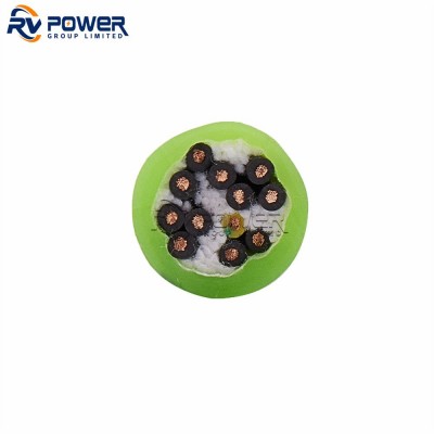
Count every conductor that must pass through the slip ring: three-phase power (3 rings), neutral (1 ring), signal pairs (2 rings each), and dedicated screens or drain wires. Add a minimum 20% spare circuits for future expansion and redundancy. Under-specifying circuit count is irreversible without replacing the entire slip ring assembly.
Each ring must be rated for the maximum continuous current of the circuit it carries, with a derating factor applied for elevated temperatures (typically 0.8 at 70°C ambient). For power rings in a 37 kW ROV system operating at 440 V three-phase, the rated current per phase is approximately 55 A; specify rings rated at a minimum 70 A to allow derating margin.
All rings must be insulated to at least 1.5 × the maximum working voltage. For 1,000 V AC systems, insulation must be rated to at least 1,500 V. Medium-voltage AEU systems (3.6 kV) require special high-voltage slip ring designs with increased creepage distances between rings.
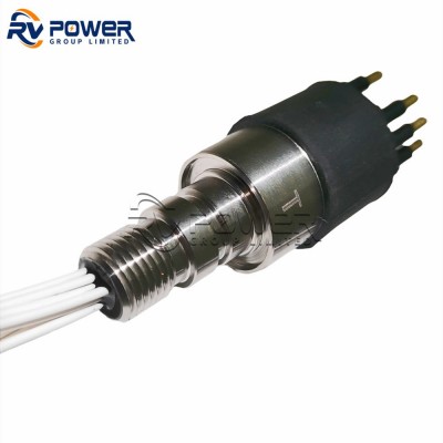
ROV winch slip rings are almost universally through-bore designs, where the drum shaft passes through the centre of the slip ring housing. The through-bore diameter must match the drum shaft OD with adequate clearance. Solid-shaft slip rings, where the rotating part is the shaft itself, are used in smaller capstan and level-wind applications.
Winch slip rings are deck-mounted and exposed to saltwater spray, deck wash, and humid marine atmosphere. A minimum IP66 rating (dust-tight, powerful water jet proof) is required. IP67 (temporary immersion) or IP68 (continuous submersion) is preferable for systems where deck flooding is possible.
Slip ring assemblies must be mounted with the rotor axis precisely aligned to the drum shaft axis. Misalignment greater than 0.1 mm causes uneven contact wear and premature failure. Most manufacturers specify a maximum radial run-out of 0.05 mm for the rotor.
Scheduled maintenance for silver graphite slip rings should include:
RV Power Group supplies slip ring assemblies and through-bore rotary joints specifically engineered for ROV winch and cable reel applications in marine and subsea environments.