ROV thrusters are the highest-power consumers on a remotely operated vehicle and the components most exposed to mechanical stress and seawater ingress risk. A wiring failure in a thruster circuit at 3,000 m depth means loss of vehicle control, a costly recovery operation, and potentially a lost vehicle. This guide covers every aspect of thruster wiring design — from conductor sizing through to connector termination and fault diagnosis.
Modern ROV thrusters use one of three motor architectures, each with different wiring requirements:
The most common thruster type for observation and light work-class ROVs. A three-phase winding is driven by an electronic speed controller (ESC) outside the motor (often in the ROV electronics pod). Wiring from the ESC to the thruster carries three-phase AC at the switching frequency of the ESC (typically 8–32 kHz). This high-frequency switching content requires cables with low inter-conductor capacitance to minimise EMI radiation.
Typical conductor size: 0.75–4 mm² per phase depending on thruster power (50–500 W per unit).
Found on older work-class ROVs, hydraulic thrusters do not require motor power wiring — the drive is hydraulic oil from the HPU. However, the proportional valve that controls flow to each thruster does require a wiring connection: typically a 24 V DC supply and a 4–20 mA or ±10 V DC analogue control signal. These low-voltage, low-current connections are less demanding than motor wiring but must still be rated for continuous subsea immersion.
Used in high-performance all-electric work-class ROVs. Similar wiring architecture to BLDC but at higher power levels (1–15 kW per thruster) and with resolver or encoder feedback cables routed alongside the motor power cables. The feedback cable is particularly sensitive to EMI from adjacent power cables and must be individually shielded.
Conductor cross-sectional area is determined by two constraints: current-carrying capacity (to prevent overheating) and voltage drop (to ensure the motor receives adequate voltage at full load).
For subsea cables, the current rating assumes the cable is immersed in seawater (which provides excellent cooling). IEC 60092-353 tables for single-core cables in seawater give conservative ratings. As a practical rule, EPR-insulated copper conductors in seawater can carry approximately 1.5–2 × their rating in free air at the same ambient temperature.
For a three-phase motor, the allowable voltage drop is typically 3–5% of nominal voltage from the ESC output to the motor terminals. For a 48 V DC nominal BLDC system, this allows a maximum drop of 1.5–2.4 V. For cable runs of 2–5 m (typical within an ROV frame), a 1.5 mm² conductor in 48 V systems is usually adequate; longer runs or higher-power motors require 2.5–4 mm².
Thruster cables must resist:
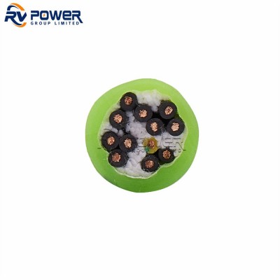
Recommended insulation: EPR (Ethylene Propylene Rubber) or XLPE. Both resist water treeing and maintain flexibility at temperatures down to -30°C.
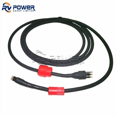
Recommended jacket: Polyurethane (PU). PU offers the best combination of abrasion resistance, hydrolysis resistance, and oil resistance for ROV internal wiring. Avoid PVC for continuous subsea service — plasticiser loss in seawater causes stiffening and eventual cracking of the outer jacket.
Cable routing is one of the most overlooked aspects of ROV electrical design. Poor routing is the leading cause of premature cable failure due to chafing and fatigue. Key routing principles:
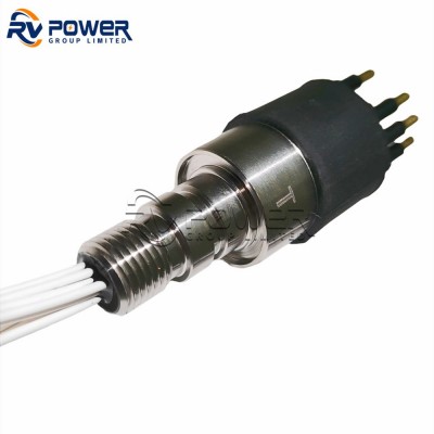
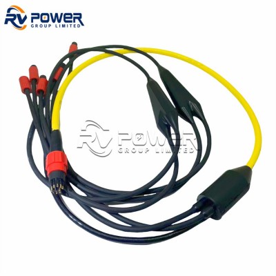
The connection between the ROV internal wiring and the thruster motor is made via an underwater mateable connector (UMC). The connector must be rated for the depth, current, and the number of mating cycles expected over the vehicle service life.
For most BLDC thruster applications, the connector carries three power pins and sometimes a thermistor or hall-sensor signal pair. Key connector selection criteria:
| Symptom | Likely Cause | Diagnostic Test |
|---|---|---|
| Thruster runs intermittently | Chafed cable, loose connector pin | Wiggle cable while monitoring current; measure pin contact resistance |
| Thruster runs in one direction only | One phase open circuit | Continuity test all three phases |
| ESC trips on overcurrent | Winding short, water ingress to motor, cable phase-to-phase fault | Measure insulation resistance (Megger) phase-to-screen; should be > 100 MΩ |
| Excessive vibration / noise | Prop entanglement, bearing failure — check cable clear of prop wash | Visual inspection, current waveform analysis |
| No response to commands | Signal cable break, connector not fully mated | Check connector locking ring, continuity of signal pair |
ROV thruster wiring is a discipline where small details — conductor sizing, jacket material, routing practice, and connector selection — have outsized impact on system reliability. The goal is a wiring installation that outlasts the planned service life of the ROV with zero unplanned intervention. RV Power Group supplies EPR and PU-jacketed motor cables, underwater mateable connectors, and custom cable assemblies for ROV thruster systems at all depth ratings.