An ROV mounted camera winch is a compact hydraulic reel assembly that integrates directly onto an ROV frame, enabling operators to deploy a camera (or sensor payload) vertically into confined spaces such as risers, J-tubes, flooded compartments, or seabed bore holes without repositioning the ROV itself. The winch spools out a composite cable carrying power, video signal, lighting control, and RS-485 communications, while an internal slip ring maintains continuous electrical continuity across the rotating drum.
This guide covers the full technical specification of a standard ROV-frame-mounted camera winch system, including hydraulic requirements, slip ring wiring, cable depth marking conventions, mechanical dimensions, and installation recommendations.
| Parameter | Specification |
|---|---|
| Camera cable capacity | 55 m (composite coax + 8-conductor) |
| ROV-to-winch tether length | 4 m |
| Weight in air | 31 kg |
| Weight in fresh water | 15 kg |
| Mounting base footprint | 500 mm x 450 mm x 12 mm |
| Overall envelope (H x L x W) | 370 mm x 570 mm x 480 mm |
| Hydraulic supply pressure | 1,500 to 3,000 psi (103 to 206 bar) |
| Hydraulic flow (minimum) | 4.2 gpm (16 lpm) |
| Gearbox ratio | 50:1 worm gearbox |
| Slip ring conductors | 8 x signal, IP68, OD 28 mm, max 200 RPM |
| Depth markers | White stripe every 10 m; green stripe at 5 m intervals |
The winch drum is driven by a hydraulic motor coupled through a worm gearbox, providing high torque at low line speeds with inherent load-holding capability. No separate brake is required. The pressure-reducing and check valve arrangement maintains stable drum tension regardless of supply pressure fluctuations from the ROV hydraulic power unit.
| Component | Type / Rating |
|---|---|
| Hydraulic motor | Low-speed high-torque, 11.48 cc/rev displacement |
| Gearbox | 50:1 worm-drive, NMRV-P063 series equivalent |
| Pressure reducing valve | Pilot-operated cartridge style (PBBB-LWN type equivalent) |
| Check valve | Inline cartridge (CXAD-XAN type equivalent) |
| Operating pressure range | 1,500 to 3,000 psi (103 to 206 bar) |
| Minimum flow rate | 4.2 gpm / 16 lpm |
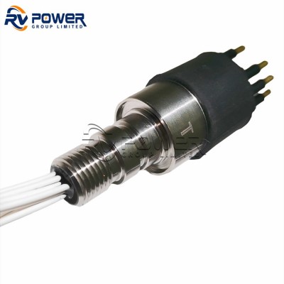
A multi-channel IP68-rated rotary slip ring is mounted at the drum axis to transfer all electrical signals continuously as the cable pays out and retrieves. The stainless steel housing is rated for full submersion at ROV working depth.

| Parameter | Value |
|---|---|
| Outer diameter | 28 mm |
| Number of circuits | 8 x signal |
| Maximum speed | 200 RPM |
| Ingress protection | IP68 (full submersion rated) |
| Housing material | Stainless steel |
| Pin | Signal | Description |
|---|---|---|
| 1 | 0 V (GND) | Signal ground / shield reference |
| 2 | +24 V | Camera and LED power supply |
| 3 | Video (coax) | Composite or HD-SDI video signal |
| 4 | Light Control A | LED dimmer channel 1 (PWM or 0-10 V) |
| 5 | Light Control B | LED dimmer channel 2 (PWM or 0-10 V) |
| 6 | RS-485 minus | Pan/tilt or camera control (half-duplex) |
| 7 | RS-485 plus | Pan/tilt or camera control (half-duplex) |
| 8 | NC | Not connected / spare |
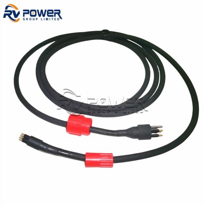
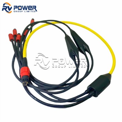
Cable routing note: The 4 m ROV-to-winch flying lead uses the same 8-conductor pinout. Ensure the video coax is impedance-matched (75 ohm) at all connectors to avoid signal reflections across the 55 m drum cable.
The 55 m camera cable incorporates a standardised depth-marking scheme that allows operators to read deployed depth directly from the drum face or via the topside camera view:
This convention is consistent with standard ROV umbilical depth marking practice, allowing cross-trained operators to read depth without additional instrumentation.
| Dimension | Value |
|---|---|
| Mounting base plate | 500 mm (L) x 450 mm (W) x 12 mm (T) |
| Overall height | 370 mm |
| Overall length | 570 mm |
| Overall width | 480 mm |
| Weight in air | 31 kg |
| Weight in fresh water (buoyancy corrected) | 15 kg |
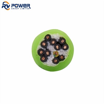
The winch is designed around a composite camera cable consisting of a central coaxial video core surrounded by eight individually screened conductors, all within a single PU or LDPE outer jacket. RV Power Group supplies compatible subsea cable assemblies and wet-mate connectors for camera winch applications.
Request Technical Data Sheet or Project Quotation
Contact RV Power Group for camera winch assemblies, compatible subsea cables, and wet-mate connectors.
Email: sales@rvpowergroup.com | Contact Form