The 13-pin Ethernet Series underwater connector addresses a persistent challenge in ROV and subsea instrument design: how to combine high-speed Ethernet data, DC power, and discrete control signals in a single wet-mateable interface without using multiple connectors or compromising signal integrity.
This article covers the design rationale, electrical specifications, typical applications, and integration guidance for the 13-pin Ethernet Series connector from RV Power Group.
A 1000BASE-T (Gigabit Ethernet) connection requires 4 differential pairs — 8 conductors. Adding DC power (supply + return = 2 conductors) and a shield/chassis ground (1 conductor) brings the baseline to 11 contacts. The remaining 2 contacts in the 13-pin configuration are reserved for discrete control signals: a relay output, a trigger input, or a status signal. This allocation covers the majority of subsea node and ROV topside/subsea junction box interface requirements in a single connector.
| Parameter | Specification |
|---|---|
| Total contacts | 13 |
| Data contacts | 8 (4 differential pairs, 100-ohm balanced) |
| Power contacts | 2 (rated 15 A each) |
| Signal/control contacts | 2 (rated 5 A each) |
| Shield contact | 1 (chassis/earth continuity) |
| Maximum data rate | 1,000 Mbps (Gigabit Ethernet) |
| Power contact voltage | Up to 300 VDC |
| Insulation resistance | >1,000 MΩ at 500 VDC |
| Dielectric withstand | 2,000 VAC, 1 minute |
| Depth rating | 4,000 m (400 bar) |
| Operating temperature | -40°C to +85°C |
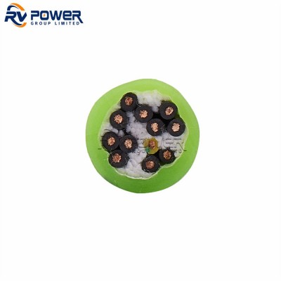
The 8 data contacts are arranged in 4 pairs with contact geometry and insulator design optimised to maintain 100-ohm differential impedance through the mating interface. This prevents the impedance discontinuity that causes reflections and limits data rate in connectors not designed for high-speed differential signalling.
Within the 13-pin insulator, data pairs are spatially separated from power contacts to minimise crosstalk from power conductor switching noise. The shield contact provides a continuous Faraday enclosure around the mating interface.
For Gigabit Ethernet performance, use Cat6 or better cable within the connector. Individual pair shields should be terminated to the chassis contact. Total cable run from the connector interface to the first network device should not exceed 100 m for standard 1000BASE-T operation.
| Parameter | Value |
|---|---|
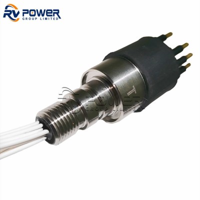
| Body material | 316L stainless steel |
| Insulator material | Polyurethane (standard), PEEK (high-temperature option) |
| Contact material | Beryllium copper, gold over nickel plate |
| O-ring material | EPDM (standard), Viton (hydrocarbon option) |
| Sealing configuration | Double O-ring face seal |
| Coupling | Threaded locking ring |
| Body OD (bulkhead) | 38 mm |
| Panel cutout diameter | 30 mm |
| Mating face diameter | 25 mm |
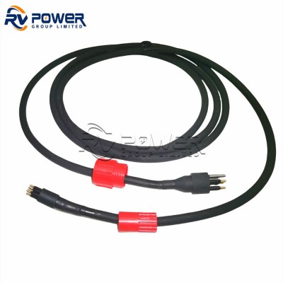
The 13-pin interface eliminates the multi-connector breakout panel that has traditionally been required at the topside end of an ROV umbilical. A single mated pair carries tether Ethernet, vehicle power bus, and tether management control in one compact interface.
Subsea data acquisition nodes connecting to oceanographic instruments (CTDs, ADCPs, hydrophones) use the 13-pin connector to pass power from the node to the instrument and data from the instrument back to the node, with discrete channels for instrument enable/disable and fault signalling.
Payload modules (sonar heads, laser profilers, manipulator cameras) that communicate over Ethernet and receive power from the vehicle power bus use the 13-pin connector as a standard payload interface, simplifying vehicle-side socket installation and payload hot-swap procedures.
Subsea Ethernet switches and media converters that connect to distributed sensor nodes or distributed control modules use 13-pin connectors on their wet-mate ports, providing power-over-connector capability alongside data.
| Approach | Connectors Required | Risk |
|---|---|---|
| 13-pin single connector | 1 mated pair | Single point of failure — but lowest complexity |
| Separate Ethernet + power connectors | 2 mated pairs | Additional penetrations, more O-ring surfaces |
| Fiber optic + separate power | 2 mated pairs | Adds optical alignment requirement; justified for >100 m runs |