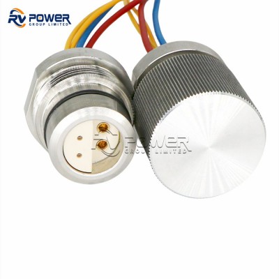
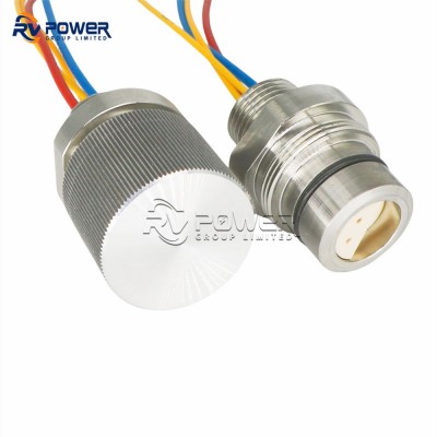
2-Core Fibre + 2-Contact Power Hybrid Underwater Connector — BCR (Bulkhead) — Overview
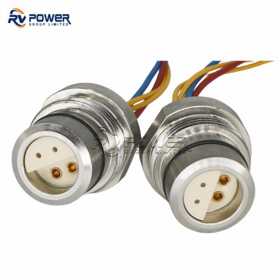
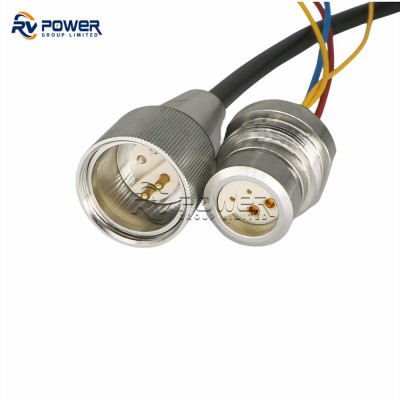
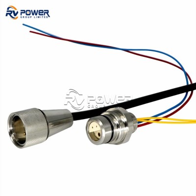
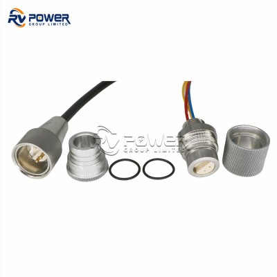
This hybrid bulkhead (BCR) underwater connector combines 2 optical fibre channels and 2 electrical power contacts in a single threaded panel-mount penetration, rated to 8,000 metres design depth. Installing through the housing wall, it provides both fibre optic data throughput and electrical power in one compact feedthrough — reducing penetration count and structural complexity on ROV pressure housings, AUV pressure vessels, and subsea junction boxes compared to using separate fibre and power bulkhead connectors.
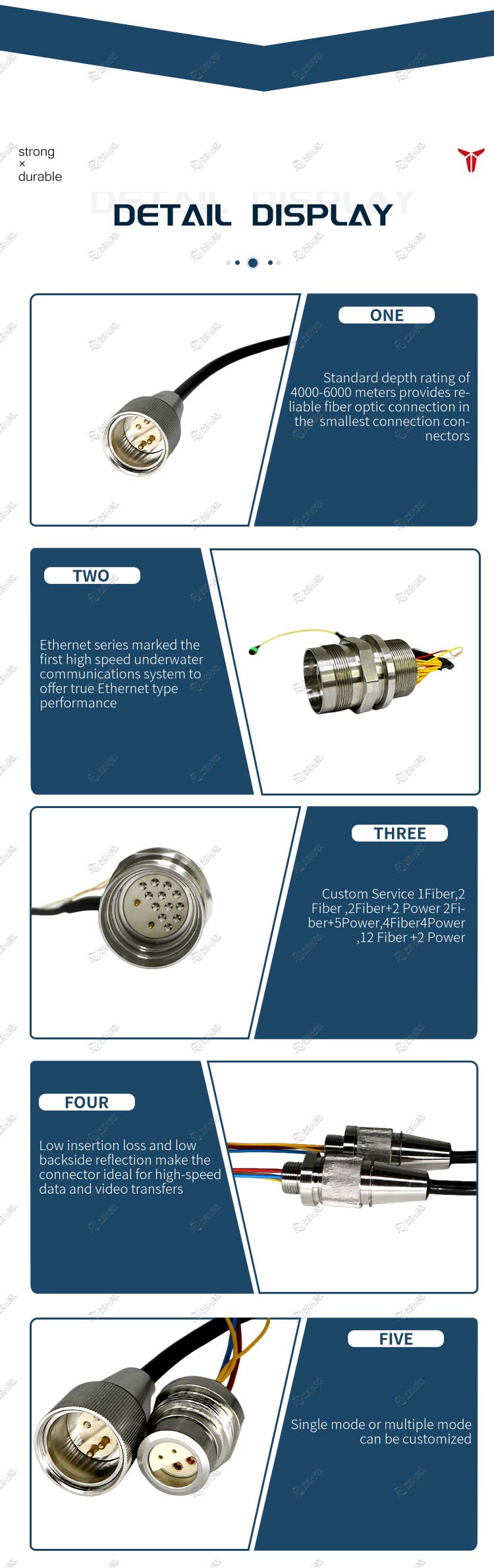
Optical channels use expanded beam ball lens technology; the mated face accepts any compatible CCP or CCR cable connector, enabling flexible harness design on the wet side.
2 Fibres + 2 Power
Hybrid Connector
8,000m Depth
Expanded Beam
BCR Bulkhead
Unlimited Matings
Key Design Features
- BCR hybrid bulkhead — single threaded penetration for 2 fibre channels + 2 power contacts; minimises housing structural penetrations
- 2 optical fibre channels — expanded beam ball lens; single-mode, multi-mode, or mixed SM+MM in same connector
- 2 electrical power contacts — rated for subsea power distribution to instruments, cameras, and actuators
- 8,000 metre depth rating — rated beyond the working depth of commercial deep-water ROV systems
- Unlimited optical mating cycles — no contact between optical surfaces; clean with swab in seconds
- Compatible with CCP/CCR cable connectors — mates with cable-mount hybrids to complete the system harness
- Nickel Aluminium Bronze / Stainless Steel / Titanium — housing material selection for deployment environment
- Reduces system cost and complexity — one hybrid BCR vs separate fibre BCR + power BCR at every interface
Technical Specifications
| Parameter | Specification |
|---|
| Optical Fibre Count | 2 cores (2 independent channels) |
| Electrical Contacts | 2 power contacts |
| Connector Type | Hybrid — Fibre Optic + Electrical Power |
| Fibre Type | Single-mode, Multi-mode, or Mixed SM+MM |
| Optical Technology | Expanded beam ball lens (air gap) |
| Standard Depth Rating | 8,000 metres |
| Connector Configuration | BCR — Bulkhead (Threaded Panel Mount) |
| Optical Mating Cycles | Unlimited |
| Housing Material (standard) | Nickel Aluminium Bronze C63000 |
| Housing Options | Stainless Steel AISI 316, Titanium Grade 2 |
| Operating Temperature | -4°C to +60°C (water); -40°C to +60°C (air) |
Typical Applications
- ROV pressure housing combined fibre data + power feedthroughs — reduce penetration count vs separate connectors
- AUV pressure vessel hybrid fibre + power penetrations for payload system integration
- Subsea junction box hybrid I/O ports for combined power distribution and fibre data routing
- Cabled observatory node chassis combined power and fibre penetrations
- Subsea completion system instrument housing hybrid optical + power feedthroughs
- Offshore renewable energy electronics housing combined power and communication penetrations
Why Expanded Beam — The Advantage Over Physical Contact Fibre Connectors
1. Tolerates Contamination — No Precision Polishing Required Subsea
Expanded beam technology enlarges the light beam to approximately 1.5 mm in diameter before it crosses the air gap between the two lenses. At this diameter, a dust particle or water droplet on the lens face occupies only a tiny fraction of the beam cross-section, causing negligible signal loss. Physical contact connectors focus light through a 9 µm core (single-mode) — a single dust particle can completely obstruct the beam and cause catastrophic signal loss. In subsea environments where cleaning is difficult or impossible, expanded beam is the only reliable choice.
2. Unlimited Mating Cycles — No Wear Mechanism
Physical contact connectors degrade with every mating cycle as the polished ferrule faces abrade against each other. Expanded beam connectors mate lens-to-lens across an air gap — there is no physical contact between the optical surfaces, no abrasion, and no degradation of optical performance over time. Unlimited mating cycles are qualified without any change in insertion loss.
3. Field Re-terminable — No Specialist Polishing Equipment Required
The spherical ball lens design allows the connector to be re-terminated in the field using a simple termination kit. The lens can be cleaned with a cotton swab in seconds. Physical contact connectors require precision polishing machines and inspection microscopes to achieve an acceptable end-face geometry — impractical on a vessel deck or at a shoreside deployment site.
4. Multiple Housing Materials for Any Environment
Available in Nickel Aluminium Bronze C63000, Stainless Steel AISI 316, and Titanium Grade 2 — allowing system designers to optimise for corrosion resistance, weight, or cost depending on mission profile and deployment duration.
5. Mixed Single-Mode and Multi-Mode in One Connector
Both single-mode and multi-mode fibres can be accommodated within the same connector body, enabling a single connector to serve mixed data (single-mode, long-distance) and video (multi-mode, short-distance) circuits simultaneously — reducing connector count and penetration points on the pressure housing.
Installation, Cleaning, and Maintenance Guidelines
Lens Cleaning Procedure
- Inspect the ball lens face under a 400× inspection microscope before every mating cycle — even minor contamination visible at this magnification should be removed before connecting.
- Clean the lens face with a lint-free cotton swab dampened with isopropyl alcohol (IPA, 99%+ purity). Allow to dry completely before mating — residual IPA causes temporary elevated insertion loss.
- Do not use dry swabs — they generate static charge that attracts particles back to the lens surface.
- Never touch the lens surface with bare fingers — skin oils cause persistent contamination that requires repeated cleaning cycles.
Mating Procedure
- Verify lens faces are clean and free of contamination on both connectors before mating.
- Align the connector keying features before applying axial force — do not rotate the connector during insertion if it is a push-pull (CCP) type.
- For threaded types (BCR/FCR), engage threads carefully and tighten to the specified torque — do not overtighten as this can distort the housing and affect optical alignment.
- Verify optical continuity with an optical power meter after mating — acceptable insertion loss should be within the connector's specified range.
Storage and Protection
- Always install protective dust caps on unmated connector faces during storage, transit, and any period when the connector is not in use.
- Store connectors in a clean, dry environment — the ball lens is robust, but contamination accumulation over extended storage will require cleaning before use.
- For long-term seabed deployment with one connector face unmated, use a pressure-rated protective cap rated to the full deployment depth.
Request a Quote or Datasheet for the 2-Core Fibre + 2-Power Hybrid BCR Bulkhead Underwater Connector
Contact RV Power Group for pricing, lead times, custom fibre count and cable options, and complete technical documentation. Engineering support available from product selection through system integration and commissioning.